Edge Impulse is the leading development platform for machine learning on edge devices. Their portal allows you to train machine learning models and deploy those models on stand alone embedded devices.
The Virtual Breadboard Edge Impulse Component can be used to aquire data from virtual or real data sources ( via EDGEY interface) and upload to a specific EdgeImpulse project via their Ingest Service.
This tutorial will walk through the essentials needed to use the Edge Impulse component to capture and upload data.
What You'll Learn
- Create an Edge Impulse project and locate the API and HMAC Keys
- Add the Edge Impulse Uploaded component to a VBB Project
- Configure the EdgeImpulse component properties
- Create test data aquisition circuits in VBB
- Capture and upload data using asynchronous mode
- Capture and upload data using synchronous mode
- View captured data in the Edge Impulse portal
Prerequisites
- Virtual Breadboard Windows Store App
- VBB Subscription
- Edge Impulse Account
Edge Impulse Projects are repositories for data and models that analyse that data. To recieve data from VBB you first need a project to send it to.
- Navigate to your Edge Import account at the Edge Impulse Portal
- Select Create new project to start the new project wizard
- Name the project TestVBB
- Click Create new project to create the named project
- Choose Something else then close the onboarding wizard
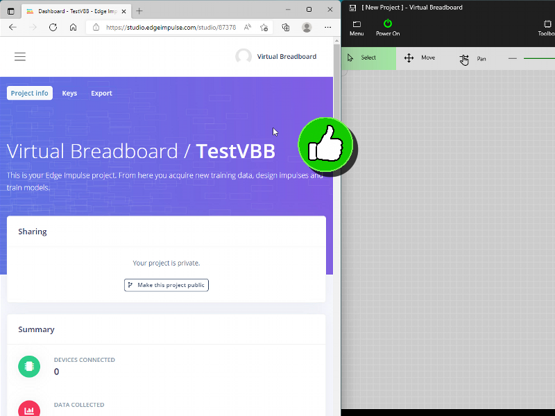
You should now have an empty project called TestVBB
To send data to this specific project you need the API KEY and HMAC key credentials to tag uploads so the data knows where to go.
We will need to copy these keys in the next step so when they are refered to follow these steps
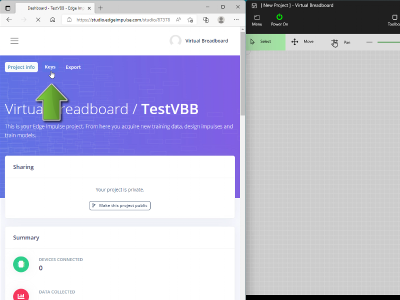
- From the Dashboard click the Keys Tab Button at the top of the page
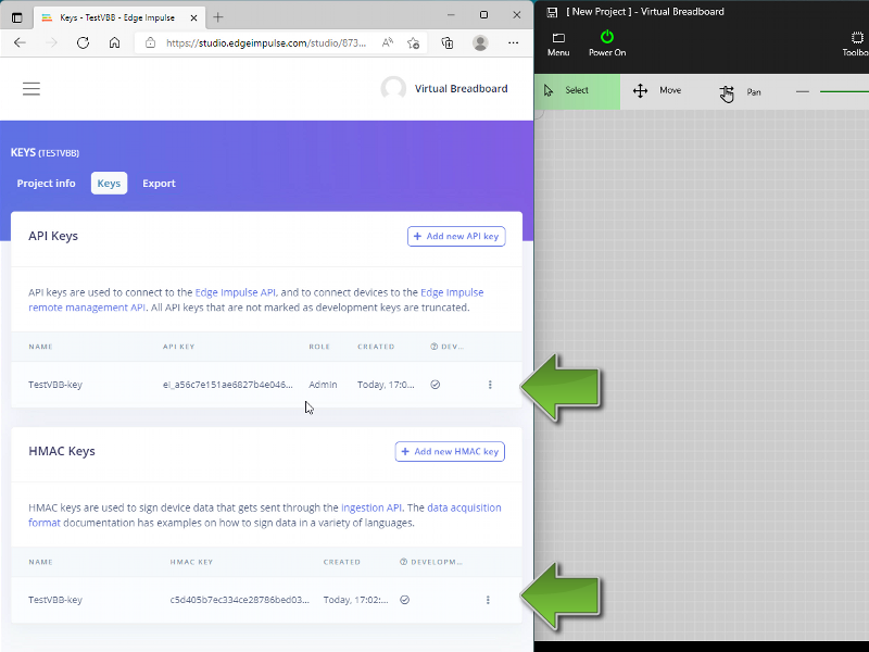
- Double Click the
API KEYto select the full key and click the copy option from the popup menu - Paste to API KEY VBB Property ( in the next step )
- Double Click the
MAC KEYto select the full key and click the copy option from the popup menu - Paste to HMAC KEY VBB Property ( in the next step )
The VBB Edge Impulse Component is used inside VBB circuits to capture and submit data by interacting with the circuit.
From a new VBB Project:
- Click the Toolbox ribbon
- Select Tiny ML group
- Click the EdgeImpulse icon to begin placing
- Move the mouse onto the Breadboard to position the component
- Click the mouse to finalise the position
The properties of a VBB Component are used to configure it's functionality and credentials.
- Click the EdgeImpulse component to show it's properties
- Select the
API KEYproperty and paste the API key from the previous step - Select the
MHAC KEYproperty and paste the API key from the previous step
Edge Impulse models are comprised of one or more Axis data streams which are sampled in the time domain at Interval milliseconds. Specific features are captured and given a Data Label against which models are trained to classify.
For more information about these elements refer to the Edge Impulse Ingest Service specification.
The VBB Component properties are populated to represent the model
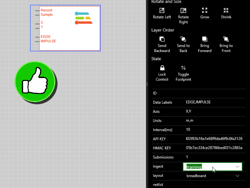
To specify the Data Label's
- Select the
Data Labelproperty - Enter a comma seperated list of Data Label names, for example EDGE,IMPULSE
This reconfigures the VBB Component with 2 additional pins EDGE, IMPULSE which are used to select the label to capture. Usually these labels should be meaningful as to the feature that is being captured but in this case it's just illustrative.
To specify the Axis'
- Select the
Axisproperty - Enter a comma seperated list of Axis names, for example X,Y
This reconfigures the VBB Component with 2 additional pins X,Y which will be wired to capture data from the circuit.
To specify the Units
- Select the
Unitproperty - Enter a comma seperated list of Unit names, for example m,m
This marks up the submitted data with the specified unit. See the Ingest Data Format for more information on the units.
To specify the Interval
- Select the
Intervalproperty - Enter 10 as the number of milliseconds beteween samples
Keep the default values of Submissions = 1 and Ingest = training
To capture data we need to wire the component into the circuit. Using the DIP and POT test components we can quickly create a capture circuit.
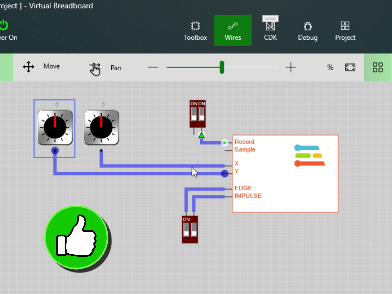
From the Buttons Group
- Place DIP components
- Wire a DIP component to each of the Record and Data Label *EDGE, IMPULSE' pins
- Place POT components
- Wire a POT component to each of the Axis X,Y pins
TIP: Change the DIP position ‘Pins' property to Top to position the Pin at the top to help organise the wiring of Data Labels.
Asynchronous Capture is where the sampled by the Edge Impulse Component every Interval simulated milliseconds which is nominally real-time ie wall clock time.
Asynchronous is implied when the Sample pin is not wired.
To capture Asynchronously capture data:
- Click the DIP switch of the EDGE Label to
HIGH - Click the DIP switch of the Record Pin to
HIGHto start the sampling - Rotate the POT components attached to the X and Y axis to generate sample data
- Click the Record DIP swith to toggle the pin low to complete the sampling and submit the EDGE labeled data
- Click the DIP switch of the EDGE Label to toggle as
LOWto finish with the Label
Repeat steps 1..5 for replacing EDGE with the IMPULSE Label.
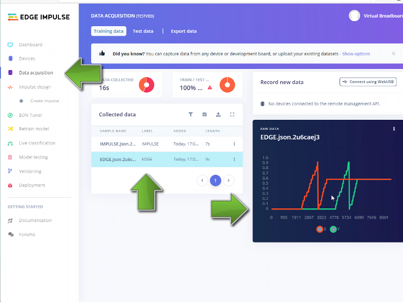
The captured data should now be available in the Edge Impulse portal
To verify upload:
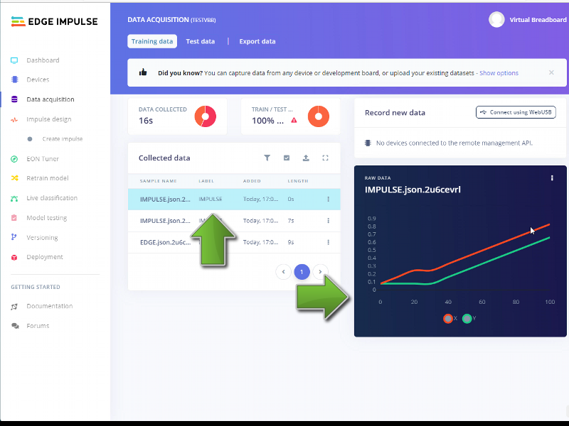
- Return to the Edge Impulse project in your browser expanding if necessary
- Click Data Aquisition from the menu
- Click a Labeled sample to visualise the data
- The sampled data should be visually displayed in a chart
Synchronous Capture is where data is shifted into the captured data set on a rising clock edge. The sample is implicitly assigned a sample time of interval milliseconds as set by the interval property.
Enable Synchronous Mode
Synchronous capture mode is enabled by wiring the Sample pin.
To enable synchronous capture mode:
- Click the DIP switch of the EDGE Label to
HIGH - Click the DIP switch of the Record Pin to
HIGHto start the sampling - Rotate the POT components attached to the X and Y axis to generate sample data
Synchronous Capture
To capture synchronous data:
- Click the DIP switch of the EDGE Label to
HIGH - Click the DIP switch of the Record Pin to
HIGHto start the sampling - Rotate the POT components attached to the X and Y axis to the next sample position
- Toggle the Sample Pin
HIGHand thenLOWto capture the next sample - Repeat steps 3 and 4 for each sample in the data set
- Click the Record DIP swith to toggle the pin low to complete the sampling and submit the EDGE labeled data
- Click the DIP switch of the EDGE Label to toggle as
LOWto finish with the Label
Repeat steps 1..7 for replacing EDGE with the IMPULSE Label.
TIP: Synchronous can be used manually as above but is primarily intended to be controlled algorithmically by circuit shift registers or unit test scripts.
The captured syncronous data should now be available in the Edge Impulse portal.
To verify upload:
- Return to the Edge Impulse project in your browser expanding if necessary
- Click Data Aquisition from the menu
- Click a Labeled sample to visualise the data
- The sampled data should be visually displayed in a chart
TIP: You can visually see the synchronous data is more uniform because it was clocked in with a fixed change per time step.
Congratulations, you have successfully uploaded data generate from VBB circuits to your Edge Impulse project.
What's next
Virtual Breadboard experts can go ahead and generate test data in Virtual Breadboard or standby for upcoming tutorials in the Edge Impulse ML series.
Upcoming Tutorials:
- Capture 2D gesture information from a TouchPad
- Train and deploy a gesture classifier to the Raspberry Pi Pico
- Use EDGEY to transmit 2D gesture information to a Live Raspberry Pi Pico and display the classification in VBB